
Description
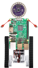
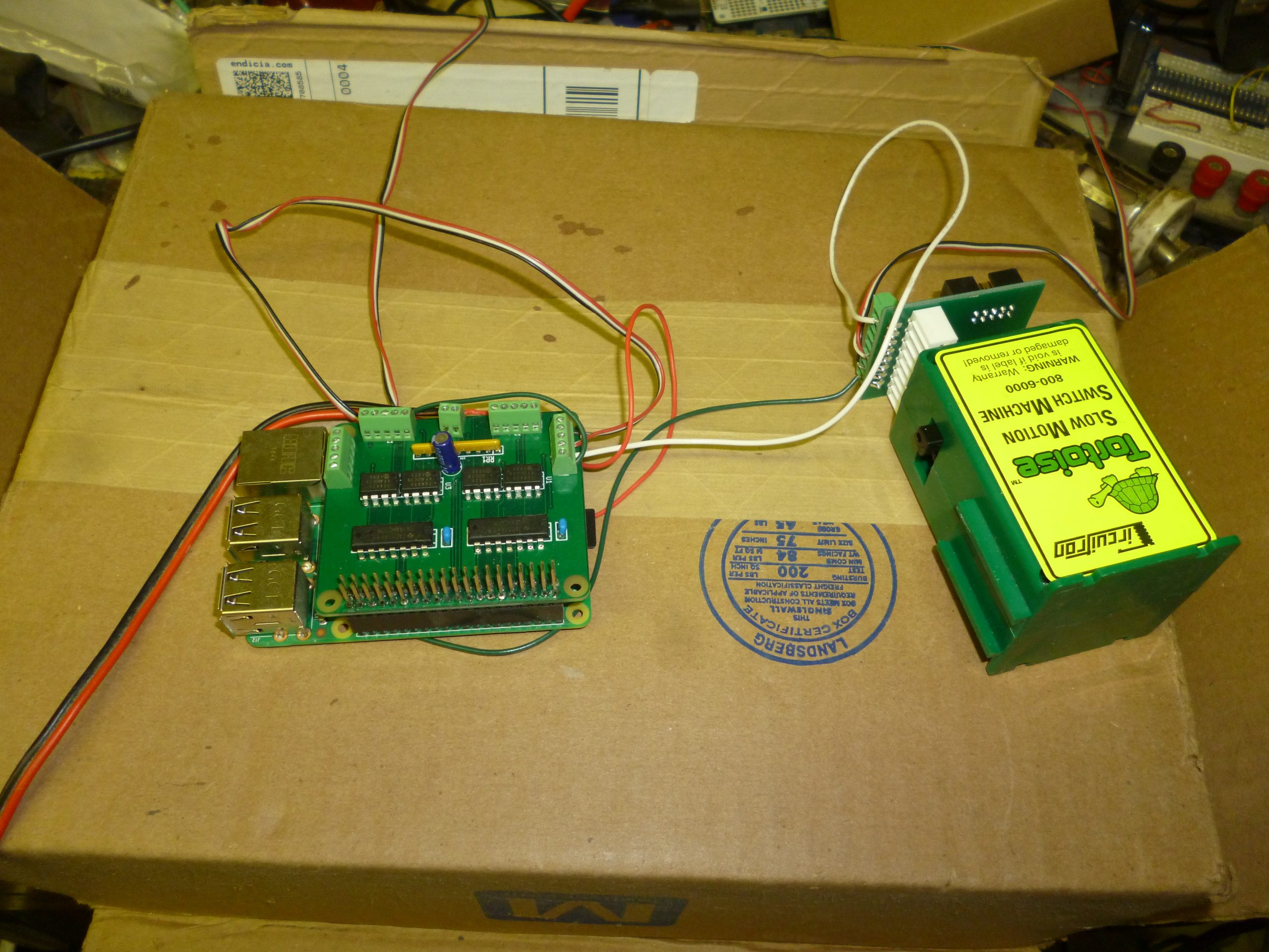
This is a circuit board to for an add-on board for a Raspberry Pi B+ that will control four stall-motor turnout motors for a model railroad. It also has sense logic to return the state of the turnouts, using one pole of the DPDT contacts in the stall-motor (typical of Tortoise stall-motors).
The circuit board uses a 40pin header socket to connect to the 40pin header on the Raspberry Pi B+ and can use a stack-through header to allow additional boards to be stacked on top of it.
GPIO Pins Used and stacking restrictions.
This board uses eight GPIO pins:
- WiringPi 0, BCM 17
-
Motor Select 1: select the position of stall motor 1.
- WiringPi 1, BCM 18
-
Motor Select 2: select the position of stall motor 2.
- WiringPi 2, BCM 27
-
Point Sense 1: return the state of the points for stall motor 1.
- WiringPi 3, BCM 22
-
Point Sense 2: return the state of the points for stall motor 2.
- WiringPi 4, BCM 23
-
Motor Select 3: select the position of stall motor 3.
- WiringPi 5, BCM 24
-
Motor Select 4: select the position of stall motor 4.
- WiringPi 6, BCM 25
-
Point Sense 3: return the state of the points for stall motor 3.
- WiringPi 7, BCM 4
-
Point Sense 4: return the state of the points for stall motor 4.
Each of the motor drive circuits is through a TC4428, which can drive up to 1.5A, which is way more needed to drive typical stall motor. It is enough to drive a pair of stall motors, wired in parallel as would be the case for a cross over.
Because this board is hardwired to use eight specific GPIO pins it is not possible to use two or more of these boards on given Raspberry Pi.
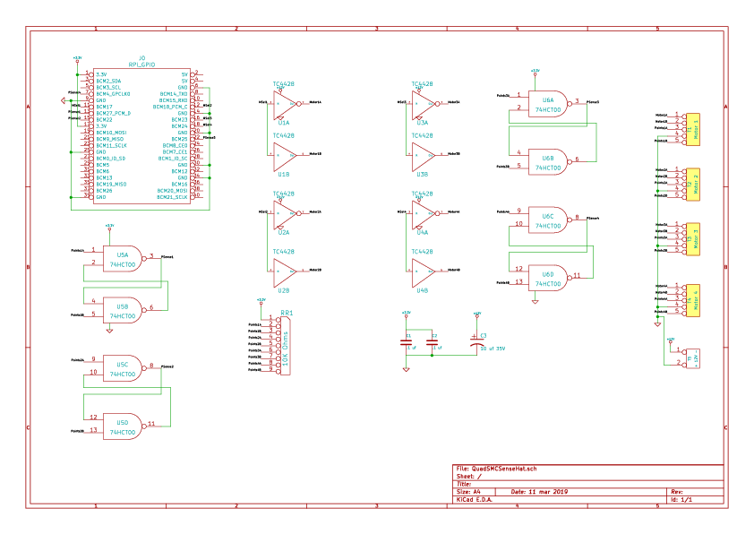
Circuit Description
This circuit contains two sections. There is an output section that contains four TC4428 chips. Each chip has a non-inverting and an inverting driver. The inputs of both drivers are connected to one of the motor GPIO pins. The output are wired to the terminal block for a one of the motors. For any given logic state of the motor control output, one of the drivers is “on” and the other is “off”, thus one motor terminal is ground and one is raised to the 12V supply. This means alternative states of the logic line will drive the stall motor in alternative directions.
The other section is a quartet of flip-flop debounce circuits, one for each of two SPDT switch contacts that report the position of the turnout points. The output of these flip-flops goes to a quartet of GPIO input pins.
Parts List
| Value | Quantity | References | Mouser Part Number | Adafruit Part Number |
|---|---|---|---|---|
| .1 uf | 2 | C1 C2 | 581-SR201C104KARTR1 | |
| 10 uf 35V | 1 | C3 | 667-ECA-1HM100I | |
| RPi_GPIO | 1 | J0 | 855-M20-6102045 | |
| 10K Ohms | 1 | RR1 | 652-4609X-1LF-10K | |
| Motor 1;Motor 2;Motor 3;Motor 4 | 4 | T1 T2 T3 T4 | 651-1725685 | |
| + 12V – | 1 | T5 | 651-1725656 | |
| TC4428 | 4 | U1 U2 U3 U4 | 579-TC4428VPA | |
| 74HCT00 | 2 | U5 U6 | 595-SN74AHC00N |
The only parts that might be substituted are J0 (the RPi GPIO Header), and T1 though T4 (the Motor terminals) and T5 (the 12 to 16 Volts terminals). The parts listed are for the stacking headers for the RPi GPIO Header, and screw terminals for the Motor terminals and the motor power terminals. Feel free to select a non-stacking header for the RPi GPIO Header and to select either pin arrays or spring terminals for the T1, T2, T3, T4 and T5.
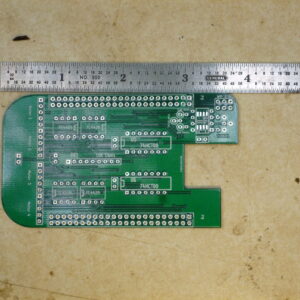
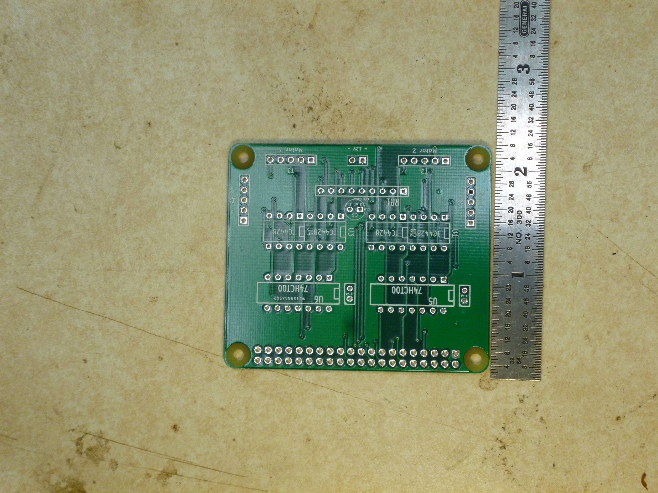
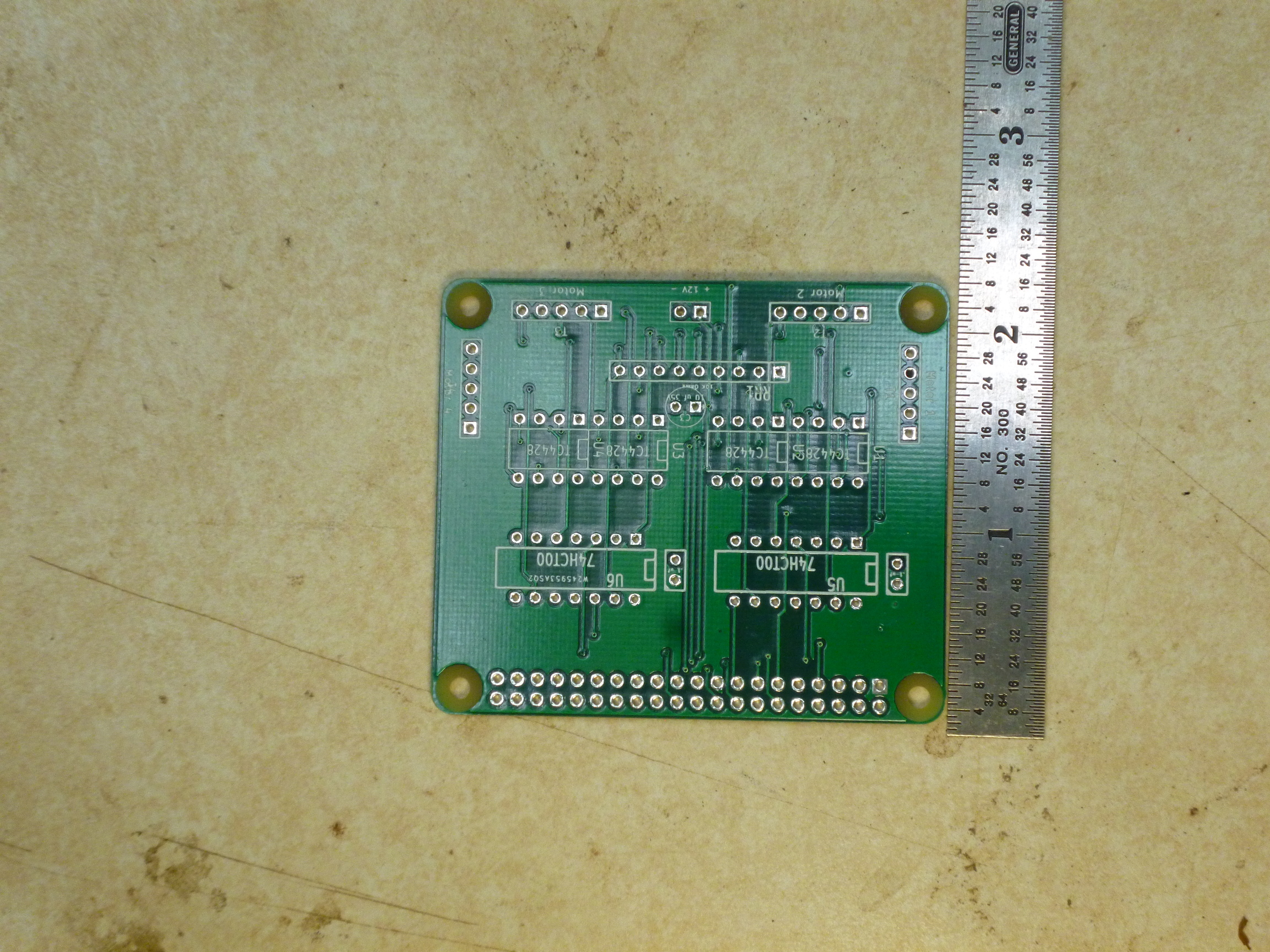
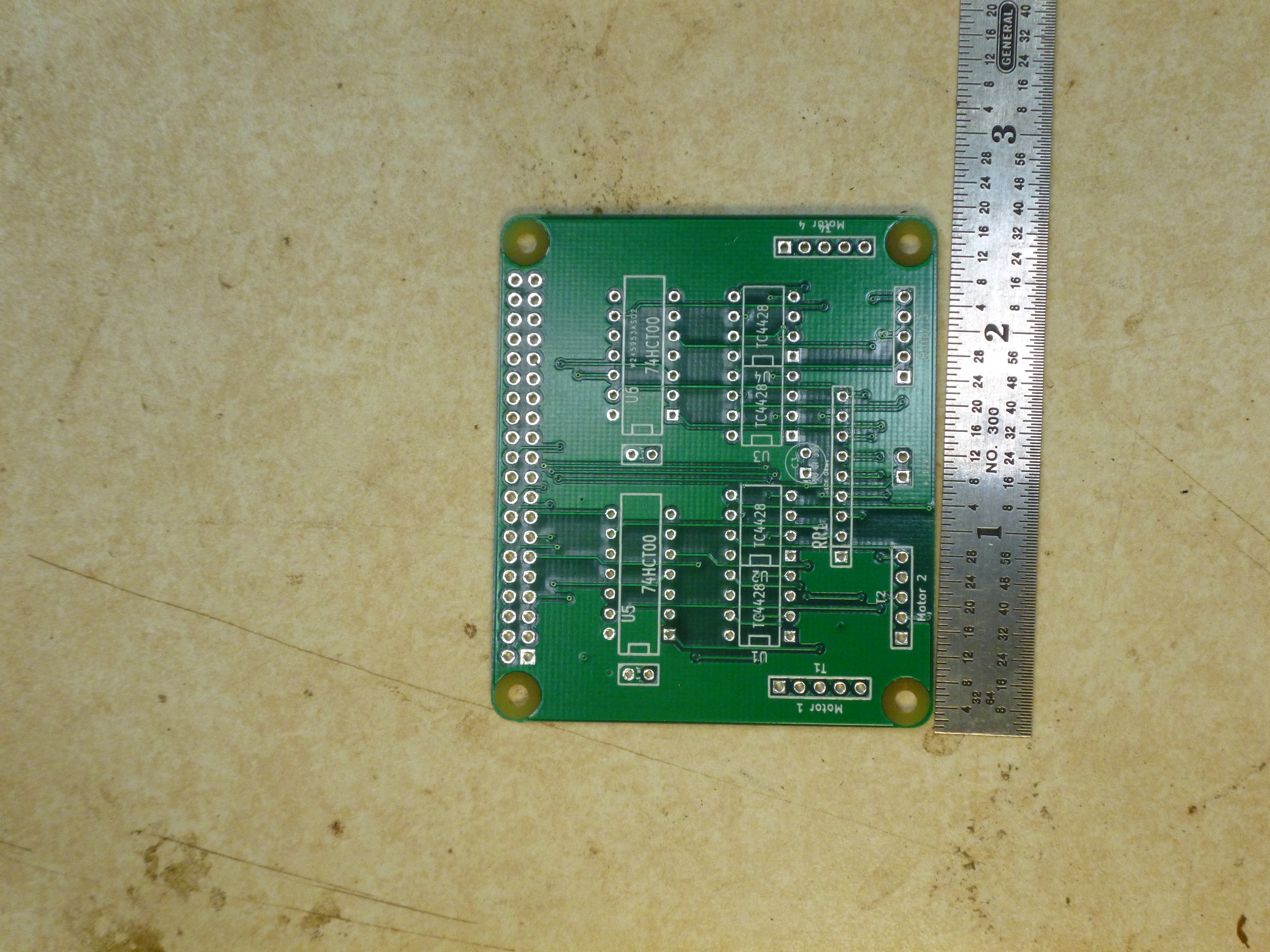
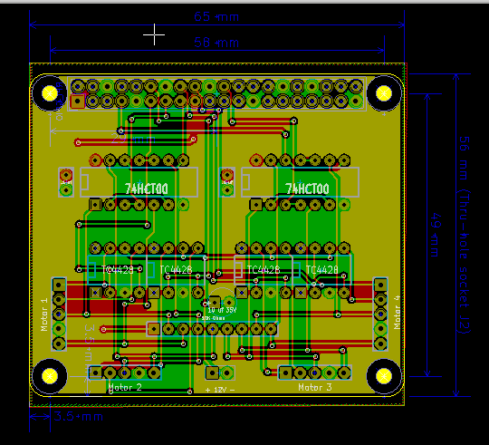
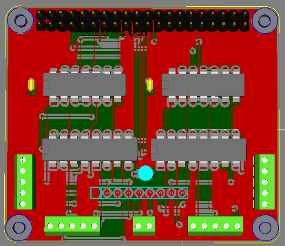
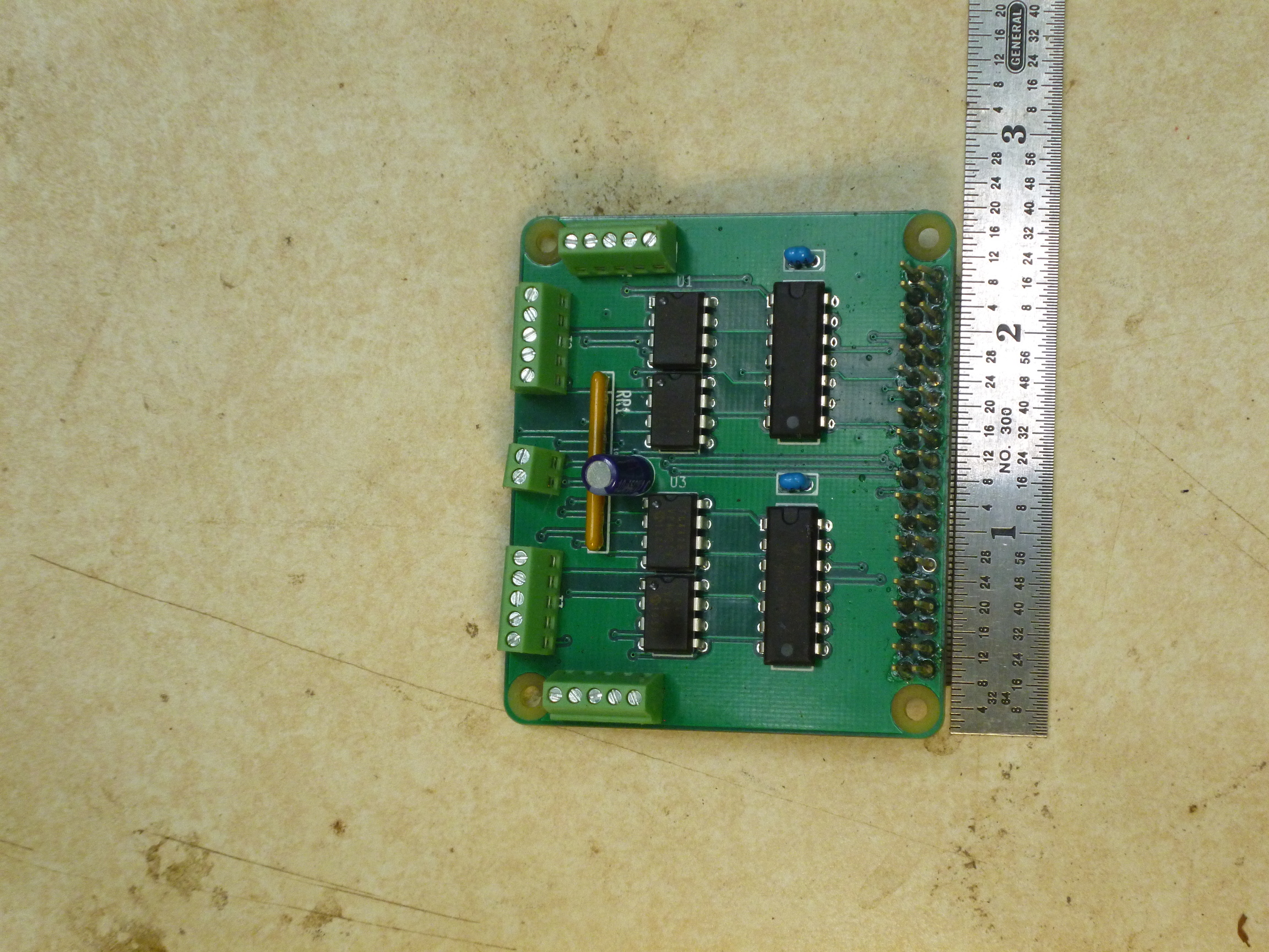
Circuit Board Layout
Board assembly is straight forward. You need to be careful orienting the ICs and the electrolytic capacitor.