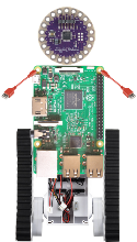
This is a circuit board to for an add-on board for a Raspberry Pi B+ that will add four 5V logic inputs and four Solid State Relays, using a MCP23008 I2C I/O expander. There is a jumper header to set one of eight addresses for the MCP23008 chip. This allows using more than one of this board or any other board featuring a MCP23008 or MCP23016 or MCP23017 chip (up to eight total).
The circuit board uses a 40pin header socket to connect to the 40pin header on the Raspberry Pi B+ and can use a stack-through header to allow additional boards to be stacked on top of it.
Circuit Description
 This circuit uses a MCP23008 to expand the Raspberry Pis I/O to 8 additional I/O pins. Four of these pins (0-3) are used to drive a pair of dual opto-isolated SSR chip and the remaining 4 (4-7) are driven by a input buffer chip that can be driven with 5V logic. The SSRs can be used to switch arbitrary trackside devices, since the output side of the SSRs are rated upto +/- 400 volts at up to 0.1 Amp (100ma). The 5V logic inputs are compatible with many sensor boards available (particularly occupancy detector circuits).
Parts List
| Value | Qty | Refs | Mouser Part Number | Adafruit Part Number |
|---|---|---|---|---|
| .1 uf | 3 | C1 C2 C3 | 21RZ310-RC | |
| ASSR-4128 | 2 | IC1 IC2 | 630-ASSR-4128-002E | |
| RPi GPIO | 1 | J0 | 855-M20-6102045 | 2223 |
| CONN 3X2 | 1 | J1 | 517-929836-02-03 | |
| 330 Ohms | 1 | RP1 | 652-4608X-AP2-331LF | |
| 10K Ohms | 2 | RR1 RR2 | 652-4605X-1LF-10K | |
| CONN 8 | 1 | T1 | 651-1725711 | |
| CONN 6 | 1 | T2 | 651-1725698 | |
| MCP23008 | 1 | U1 | 579-MCP23008-E/P | |
| 74LV125AN | 1 | U2 | 595-SN74LV125AN | |
| Value | Qty | Refs | Mouser Part Number | Adafruit Part Number |
The only parts that might be substituted are J0 (the RPi GPIO Header), and T1 and T2 (the I/O terminals). The parts listed are for the stacking headers for the RPi GPIO Header, and screw terminals for the I/O terminals. Feel free to select a non-stacking header for the RPi GPIO Header and to select either pin arrays or spring terminals for the T1 and T2.
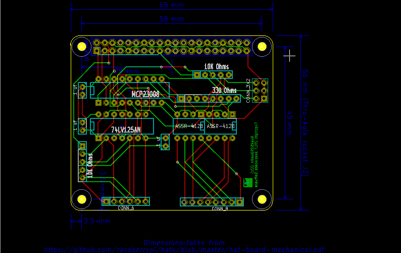
Circuit Board Layout
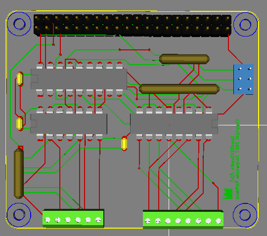
 Board assembly is straight forward. You need to be careful orienting the ICs, noting that the SSRs are oppositely oriented from the other ICs. Also the SIP resistor arrays need to be carefully oriented — the dot marks pin 1, which is indicated on the board with a square pad. The first batch of the boards I ordered used the wrong PCB modules for the terminals and the holes are too small for the screw terminal pins to go all the way in. They can be "jammed" in enough to be soldered. Pin arrays fit a little better, but still need some effort to seat. The next batch I order will not have this problem.
Downloadables and Software Support
Full design information is available on GitHub here: https://github.com/RobertPHeller/RPi-RRCircuits/tree/master/QuadSSSQuadIn.
This board is supported by the Model Railroad System OpenLCB_PiMCP23008 daemon. A basic XML file for it is included in its GitHub folder.