
Raspberry Pi Junction: How to Use a Raspberry Pi on your Model Railroad
Tags: Model Railroad, raspberry pi, The Country Robot


What it is
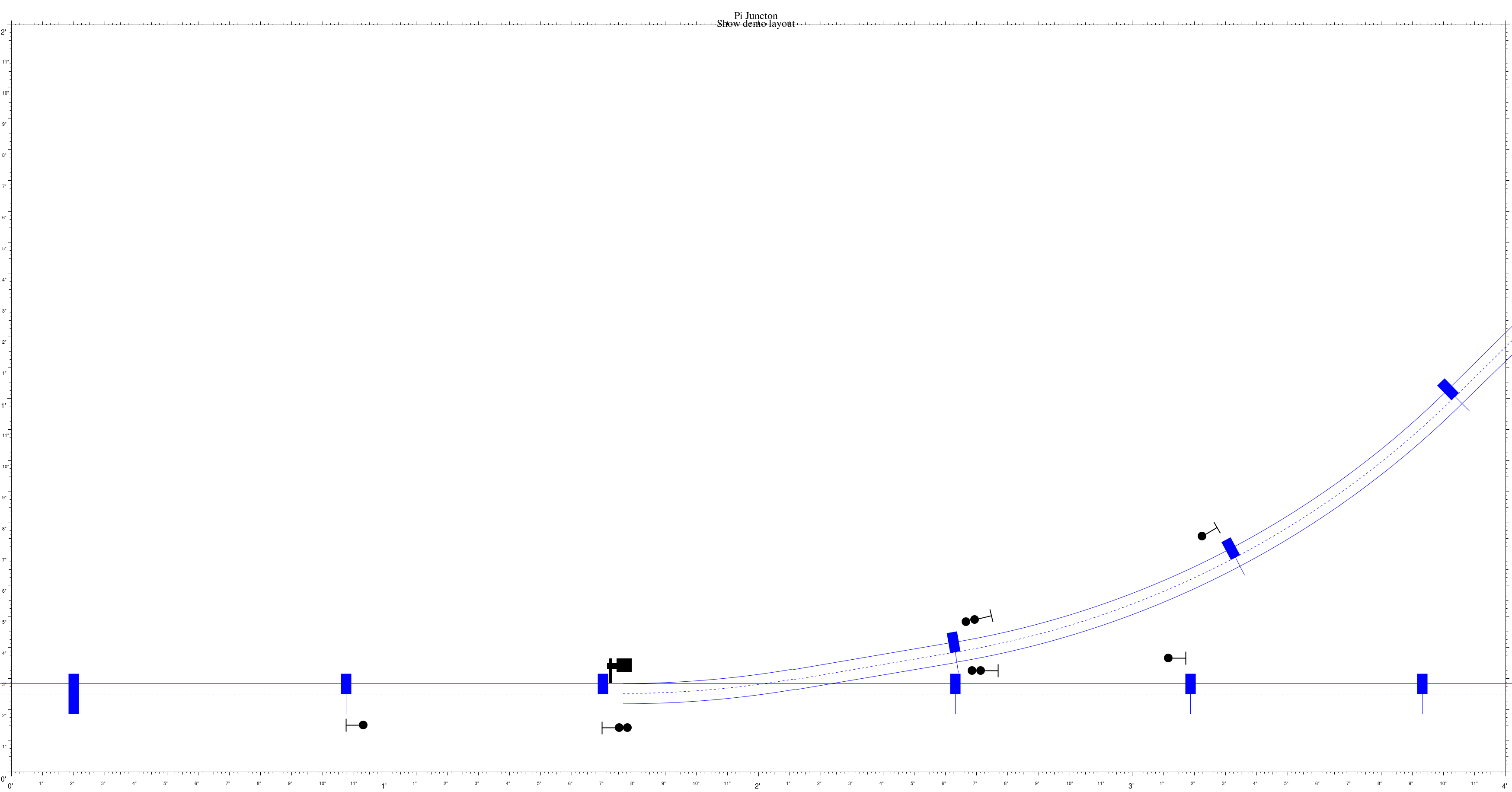 This article is about Raspberry Pi Junction, a simple demo layout featuring a simple interlocking off the main line at Mile Post 314 that goes past the Mad Hatter Pie Shop.
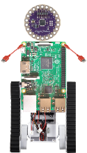
The junction itself and the adjacent blocks are controlled by a Raspberry Pi Model 3 B+ (sirtopemhat), which has five HAT (Hardware Attached on Top) boards.
The HAT boards interface to the layout control elements on the layout. The layout control elements include one Circuitron Tortoise stall-motor switch machine, a Circuits4Tracks Quad Occupancy Detector, and six color light signals. Also the lighting of the Mad Hatter Pie Shop can be controlled by the Raspberry Pi.
The HATs
Each of the HATs provide the hardware to interface the Pi to the control elements on the layout. This is done using the GPIO pins on the Pi’s 40-pin GPIO header.
- RTC Hat
- This is just a DS1307 Real Time Clock module, used to keep time when the Pi is shutdown.
- SMCSenseHAT
- This HAT controls the Circuitron Tortoise stall-motor switch machine and sense its position.
- QuadSSSQuadIn
- This HAT provides the inputs for the Circuits4Tracks Quad Occupancy Detector and also controls the structure light for the Mad Hatter Pie Shop.
- MCP23017Hat
- There are two of these boards and they control the lighting of the signals.
SMCSenseHAT
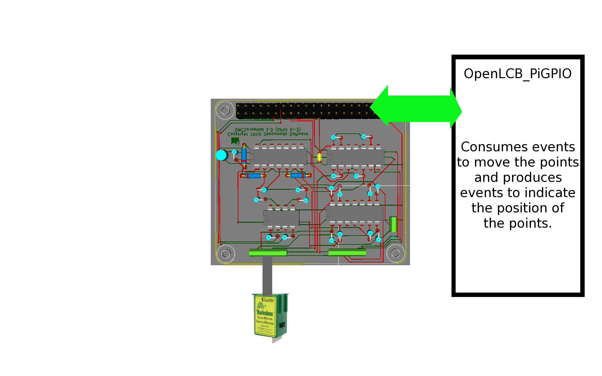 The SMCSenseHAT board uses GPIO pins to control and sense two Circuitron Tortoise (or similar) stall-motor switch machines. Two GPIO pins drive the stall-motors (one for each stall-motor) and two GPIO pins return the point state for the stall-motors (one for each stall-motor). The OpenLCB_PiGPIO program implements a LCC/OpenLCB node that interfaces this HAT to the LCC/OpenLCB network, consuming events to activate the stall-motor(s), and produce events to indicate the point position.
QuadSSSQuadIn
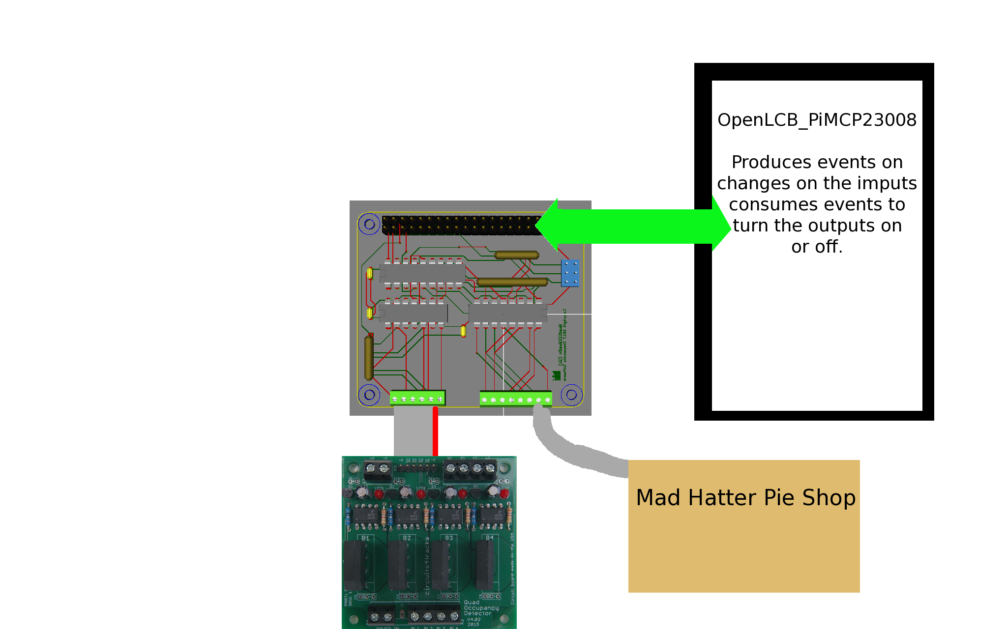 The QuadSSSQuadIn uses a MCP23008 I2C I/O expander chip to implement four 5V Logic inputs and four SSR (Solid State Relay) outputs. The four inputs are connected to the Circuits4Tracks Quad Occupancy Detector’s outputs and one of the SSR outputs controls the lighting of the Mad Hatter Pie Shop. The OpenLCB_PiMCP23008 program implements a LCC/OpenLCB node that interfaces this HAT to the LCC/OpenLCB network, producing events for block occupancy and consuming events to turn the Mad Hatter Pie Shop’s light on and off.
MCP23017Hat
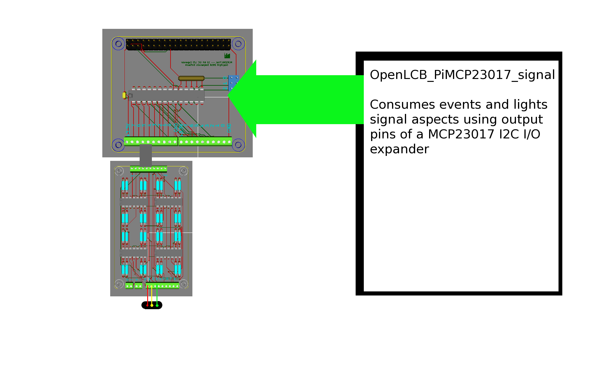 The MCP23017Hat uses a MCP23017 I2C I/O expander chip to implement 16 3.3V GPIO pins, in two banks of 8. There are two of these HATs and they are used to drive the 22 LEDs in the 6 signals. There are three octal (8) LED driver boards to actually drive the LEDs. There are two processes running the OpenLCM_PiMCP23017_signal program, creating two LCC nodes to handle all of the signals.
The LCC/OpenLCB network
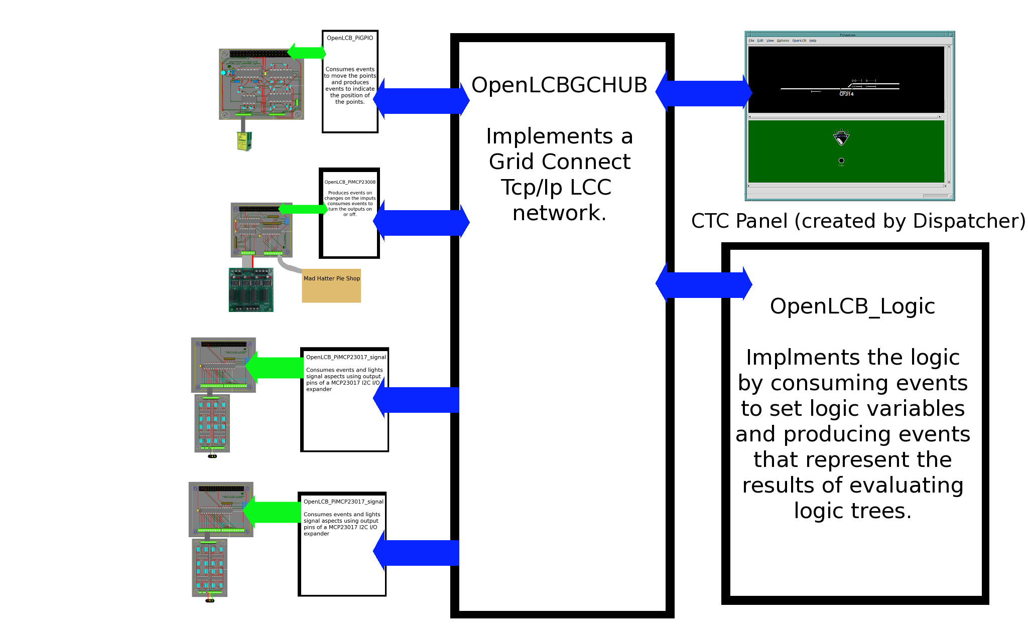 On the software side, the Raspberry Pi implements a "virtual" LCC/OpenLCB "network". The Model Railroad System from Deepwoods Software includes daemon programs that interface to the HATs and to provide a virtual network for them to communicate over. This includes a Tcp/Ip "hub" daemon, and a set of OpenLCB "node" daemons, along with a program, Dispatcher, that can be used to to create a CTC (Dispatcher) panel program. Each of the node daemons interfaces to one HAT, plus a pair of additional node daemons, one to implement the "logic" of the layout and one to implement a CTC (Dispatcher) panel. All of the nodes communite with each other through the "hub" daemon by passing LCC Event Report messages to each other.
Traction control — Driving the loco
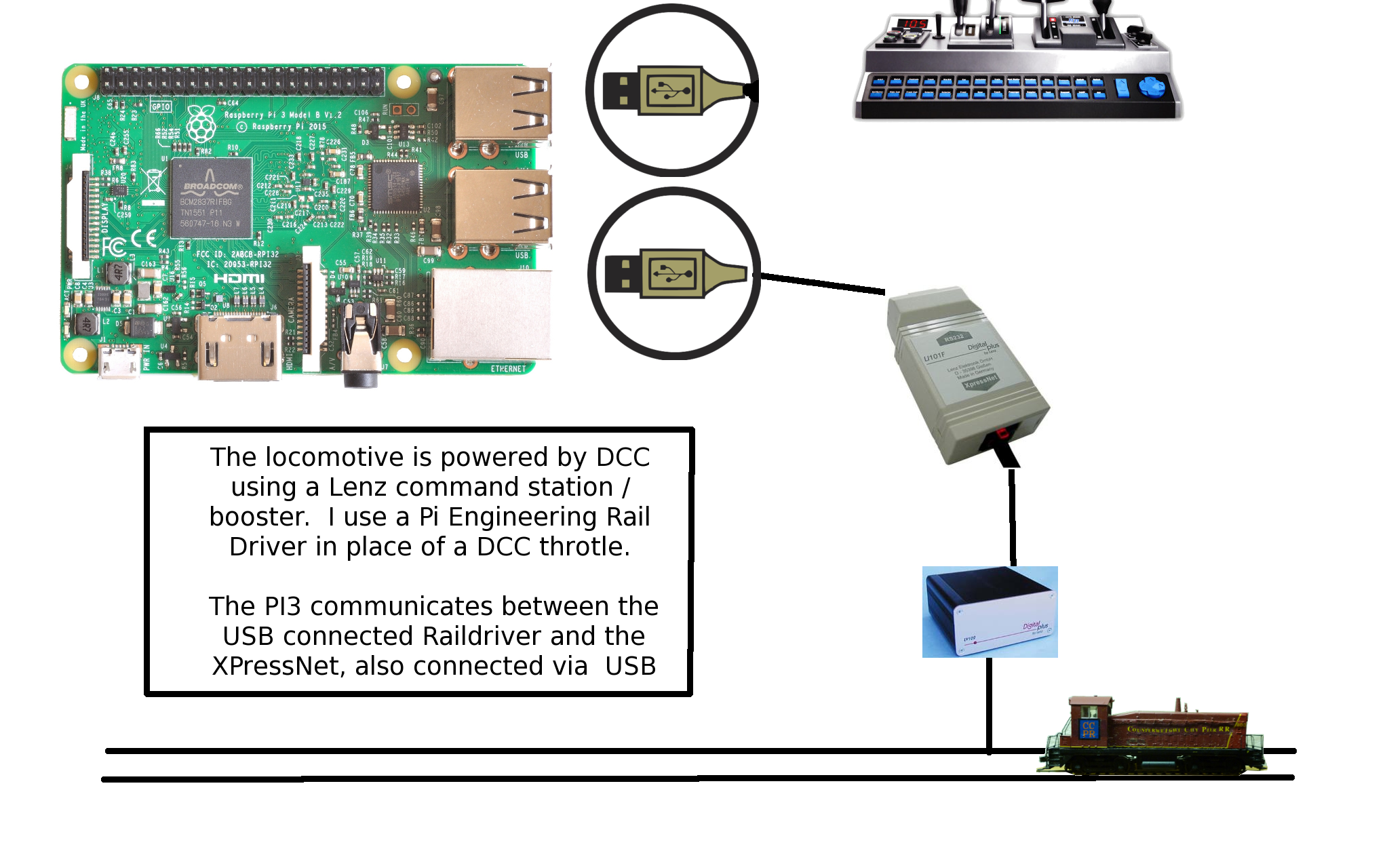 The locomotive is powered by DCC using a Lenz command station / booster. I use a Pi Engineering Rail Driver in place of a DCC throtle.
The Rail Driver is a USB HID device and I use the Model Railrail System raildriverd daemon to drive it, using the Raildriver Support library and use the XPressNet library to talk to the Lenz command station / booster unit.